
Last month I had just about finished the cylinders and crank, and about to start on experimenting with casting the alloy parts.
 Well, after thinking about it for a while I decided to re-design the parts so that I could make them out of sheet and other materials using my little hammer. Casting is OK, but I wanted to get this engine finished and I assumed that casting parts would be a lot of trial and error, so fabricating would be easier. The crankcase was hammered into a U shape from 3mm alloy sheet, with another piece of 3mm bonded to it with epoxy to provide the mounting base for the cylinders. The end covers were also cut from 3mm alloy with the bearing housings turned from bar and pressed into the end plates. Once hammered into shape, all the parts were machined on the mill to give clean joint faces and to make sure that the whole thing was square and dimensionally accurate.
 Here's a couple of pictures with the crankcase roughly assembled, with and without the end plates - the copper pipes are stubs for the inlet manifolds, more on this presently
The two halves of the crankcase are dowelled together to ensure they stay in alignment, and the end covers also have dowels for the same reason - this proved to be a good plan, as I lost count of the number of times I had to assemble and dismantle the whole thing while checking that all the bits fitted properly

The next job was to press the two halves of the crankshaft together on the big end pin. This proved to be a real challenge for several reasons. First, the difficulty of holding the two halves of the shaft in line with each other while pressing the pin into place: I ended up with one half in the headstock chuck on the lathe, and the other half in the tailstock chuck, then fiddled and faffed until the big end hole was lined up (done mostly by eye).
 |
| Very fuzzy pic of the innards of the oil pump |
 |
| Oil pump mounted on end cover and gears in place |
 |
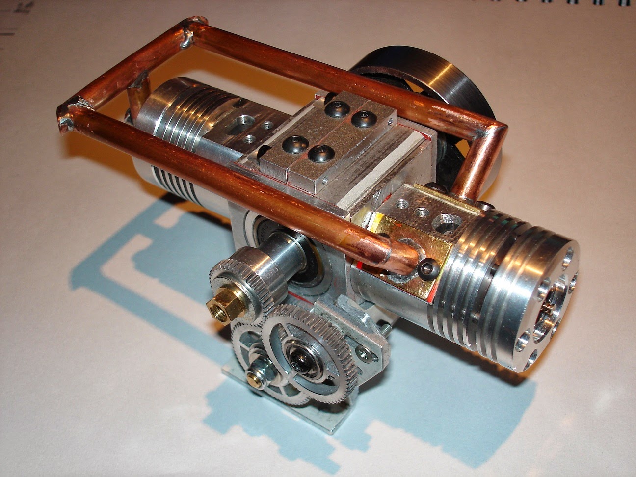
| Final assembly with flywheel and transfer manifold |
Because the big ends on the conrods are not split, they had to be assembled when the big end pin was pressed into the crank. This left the crank with pistons hanging out either side, which is why the split crankcase was needed - its the only way to assemble the whole caboodle together.
So, first assemble the oil pump to the end cover; next, press the ball races on to the crank; put the crank into the crankcase and bolt the two halves together; then insert the pistons into the cylinders (very fiddly business with the two rings on each piston) and bolt the pistons to the crankcase. Does the whole thing still turn over? Yes, though a bit stiff as expected. Fit the oil pump drive gears and adjust the backlash, squirt some oil into the sump and the cylinders, and we're ready for a bit of a test run with the ol' Black and Decker.
 |
| ... and seen from the other side |
Next up, the transfer manifold. I experimented with all sorts of options for this - it has to carry the pressurised mixture from the pre-charge cylinder into the firing cylinder, with pressures of around 10 bar, so it has to be pretty sturdy. I ended up fabricating it from some copper pipe with soft soldered joints - not very efficient, but for this prototype it will do. Last item is the flywheel, made from a chunk of steel pipe with a plate welded across, it ain't pretty but it works. Last addition, a piece of copper plumbing pipe to act as a silencer and catch the exhaust gunk.
 |
| Finished and ready to run |
Glow plug in and carburettor mounted on a short piece of flubber hose - quicker than making a proper manifold. I have made my own carburettor, but a) its huge, and b) I have no idea if it will work so if the engine fails to start I won't know if its the carb or the engine.
Right. Clamp the whole thing to a bit of wood in the vice, attach the fuel tank and various bits of pipe, and give it some with the power drill. Several hours later, it eventually started and ran for a few seconds. I know it was actually firing, because the cylinder head and exhaust got hot, but it turns out that starting easily is not a feature of this engine. After many hours of fiddling I eventually got it running for a few minutes (the video goes on a bit, and its all much the same...)
It may not be obvious in the video, but by this time the two ends of the crankshaft had become slightly deranged, resulting in massive vibration (enough to shake all the tools off the bench) which rapidly began to shake the fabricated crankcase apart. Not keen on seeing how long it takes before hot bits of oily metal start flying through the air, so it probably won't be running again. I've learned a huge amount during the build, and seeing it actually running has prompted me to set to work designing another one - this will have two cylinders and better port timing, plus a bigger flywheel, as I think these are the main reasons why the engine was so hard to start. For a taster of what the new engine will be like, google for 'Commer TS3', and if you tell me I'm mad I'll slap you with a kipper.
That's all for this month, I need a rest and time to clean up the workshop :-)